自動車のCADデータを使って風洞シミュレーションをSTAR CCM+でやってみよう。実務的な観点から、車のCADだけ受け取って、風洞はCCM+上で自分で定義すると想定する。
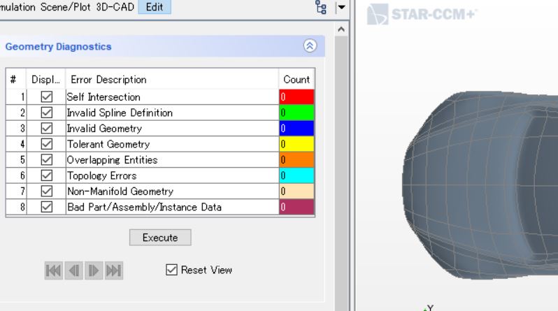
CADファイルはサーフェスメッシュとしていきなり読み込むこともできるけど、ここでは (1)風洞パーツの作成と (2)半分だけ解析するめにシンメトリ面を導入してスライス を行うために、“CADモデル”としてファイルをインポートしてください。CADモデルを取り込んだらジオメトリチェックは忘れずに。(もちろん、後から修正できるけど…)
Some handy tips for a simulation of car wind tunnel with STAR CCM+ are introduced in this page. In practical terms, car CAD blocks might be provided, but need to create a wind tunnel in CFD to simulate a wind tunnel test.
We can import a CAD file as a surface mesh, but import it as a “CAD model” because (1) a wind tunnel part is needed, and then (2) the CAD model will be sliced half with a wind tunnel part to save the computational cost. Recommend that you should execute “Geometry Diagnostics” before anything else.
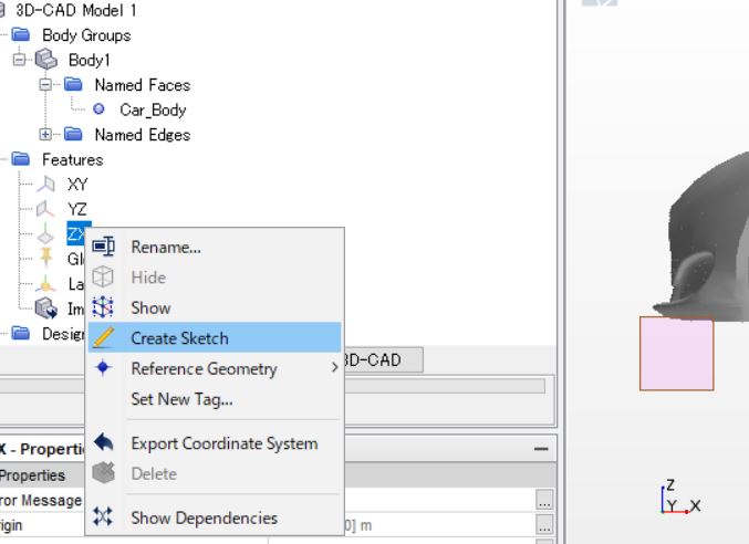
風洞パーツを作る方法もいろいろあるけれど、今回はシンプルな直方体なのでスケッチツールを使いました。面を定義して押し出し、で簡単にできます。(”Simulation”メニューのパーツからも作れるけれど、次に紹介するシンメトリ適応のために”3D-CAD”メニューで作るのがポイント。)
Several ways to create a wind tunnel part, then I prefer the Sketch tool in this case. You can simply define the plane and extrude it in the “3D-CAD” menu.
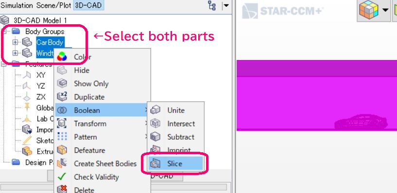
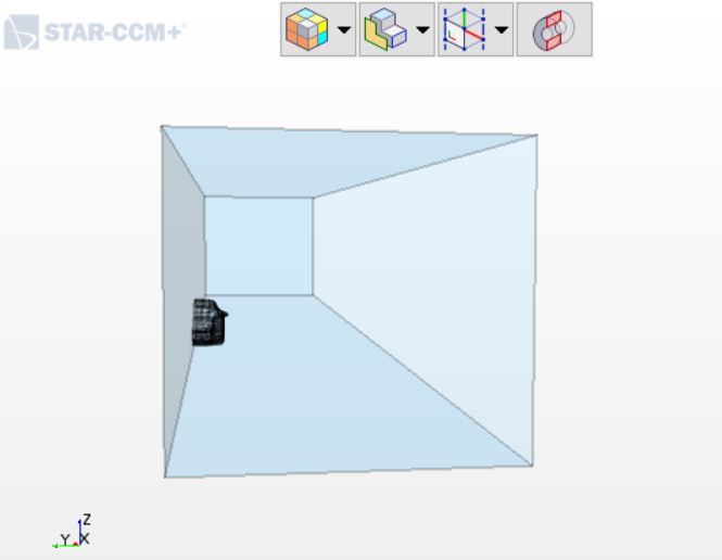
自動車は左右対称なので、解析対象の流れ場も左右で同じ状態になる、という仮定のもと、シミュレーションコスト削減のために半分だけにして解析を行うことはよくある。これは3D-CAD 編集画面から簡単に行えます。自動車のパーツと風洞のパーツ、両方を選んだ状態で「ブーリアン」→「スライス」。分割面は「スケッチ平面」で変えられるので、プレビューで解析対象が左右に分割されていることを確認したから実行。
It can be assumed that there is a symmetric flow field because the car model is symmetric. Therefore, the right (or left) side simulation is enough to obtain physical quantities like force, velocity, etc.
Select both the car model part and wind tunnel as shown in the image below. You can change the cross-section (slice plane) by switching “Sketch plane” (e.g. from XZ to YZ). Make sure your model is cut off left and right side instead front and back in a preview window.
A half model is obtained then.
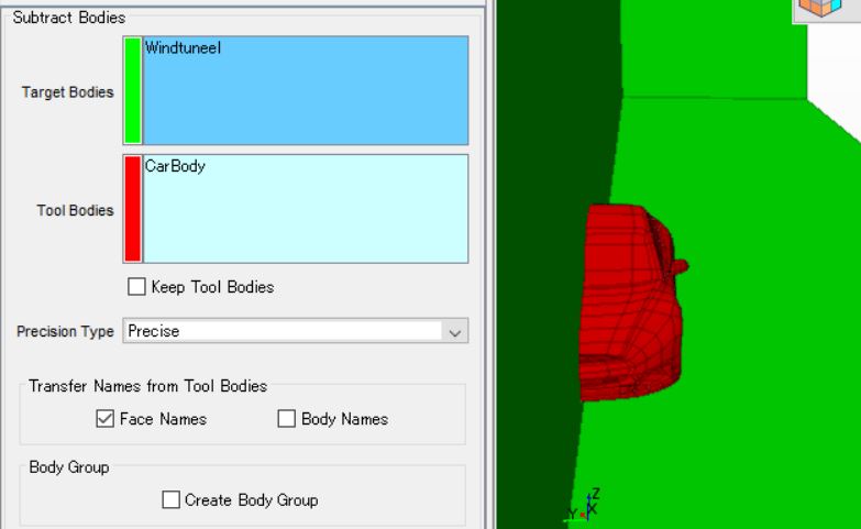
3D-CAD メニューを閉じる前に、ここで、作成した風洞パーツに対して車のパーツ部分をくり抜く作業をします。半分にした時と同様に、両方のパーツを選択した状態で「ブーリアン」→「Subtract(日本語だとくり抜き、とかかな?)」をクリック。空気の流れ場から自動車がある部分をくり抜くので、下の画面で;対象が風洞パーツ、ツールが車のパーツになるようにして実行。ここまでできたら、シミュレーションメニューに戻って、残りの手順はいつも通り。
Need to remove the area of vehicle body form the flow field, so the “Subtract” function is useful. Select both parts and right click, “Boolean” > “Subtract”. Note that the area of car body is subtracted from the wind tunnel. It means that the part of wind tunnel is the target body, and the vehicle CAD part should be selected as a tool body as shown in the image below. Then close the “3D-CAD” window.
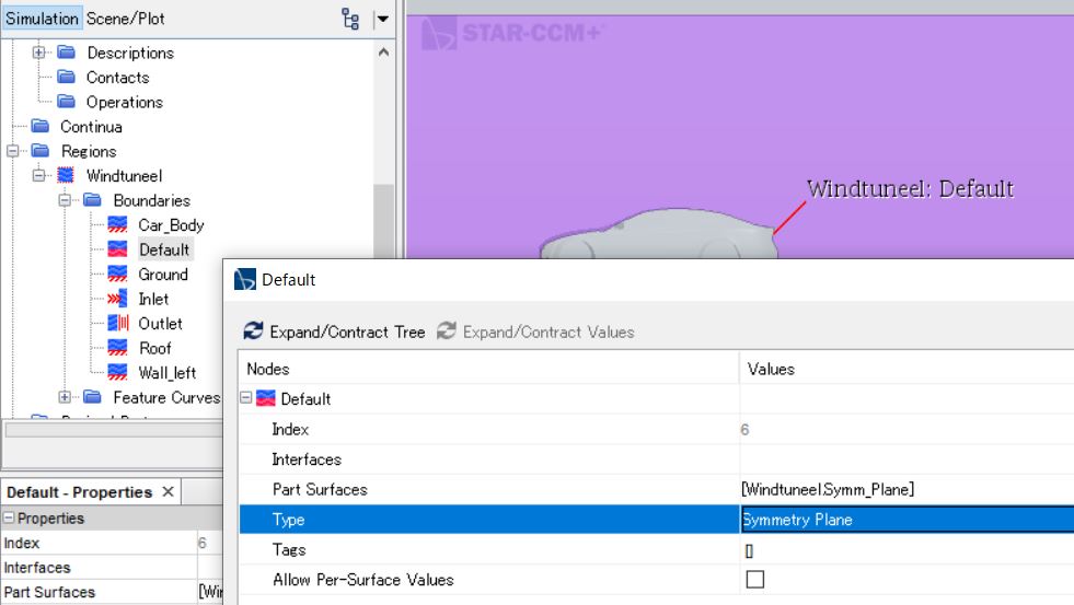
Following process is same as usual, but note that you have a symmetric place. Don’t forget to define it as “Symmetry Place”.
- Inlet : Velocity Inlet
- Outlet : Pressure Outlet
- Symmetry Place : Symmetry Place – I had named all surface (like Inlet, Outlet, etc.) before slicing, so only this plane is named as default by STAR CCM+. Of course, you can change it.
メッシュをはる前に、基準サイズや成長率なんかはモデルの大きさから変更する、のは当たり前だけど、無駄をなくすために「カスタム制御」も編集します。
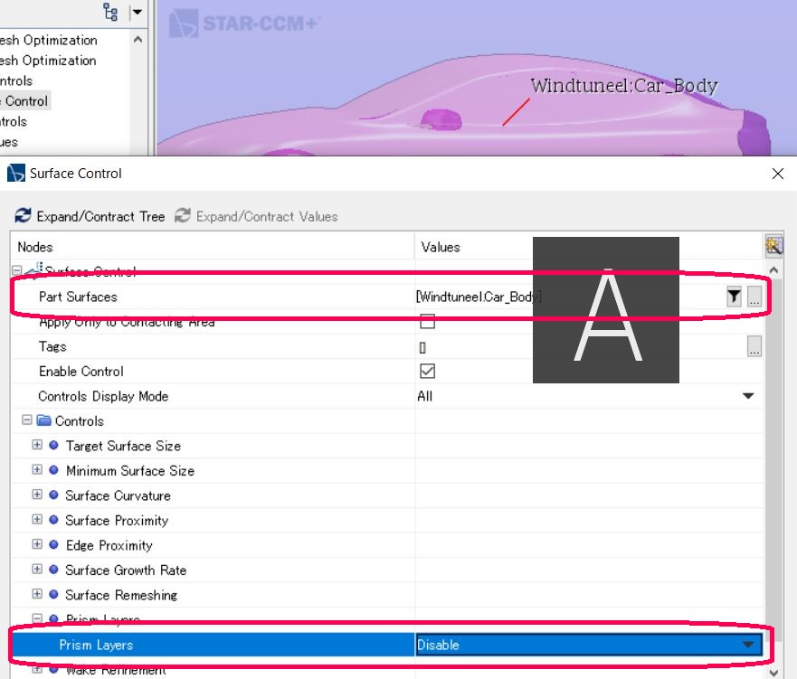
個体領域はプリズムレイヤーがあっても意味がないので、車の部分に対してプリズムレイヤーが無効になるように設定。これは、カスタム制御に「サーフェスメッシュの制御」を新規に追加してプロパティを変更することで設定が可能。
Before executing Automated Mesh, normally we change the Base Size, Prism Layer Total Thickness, etc to optimise them based on the model size. In addition to this basic “Default Controls”, recommend to use the “Custom Controls” as well.
For instance, solid bodies don’t need the prism layer, so disable it form the car body part. Create “Surface Control”.
- Part Surface: select your solid parts (in this case, Car_Body surface)
- Prism Layers: Disable
